

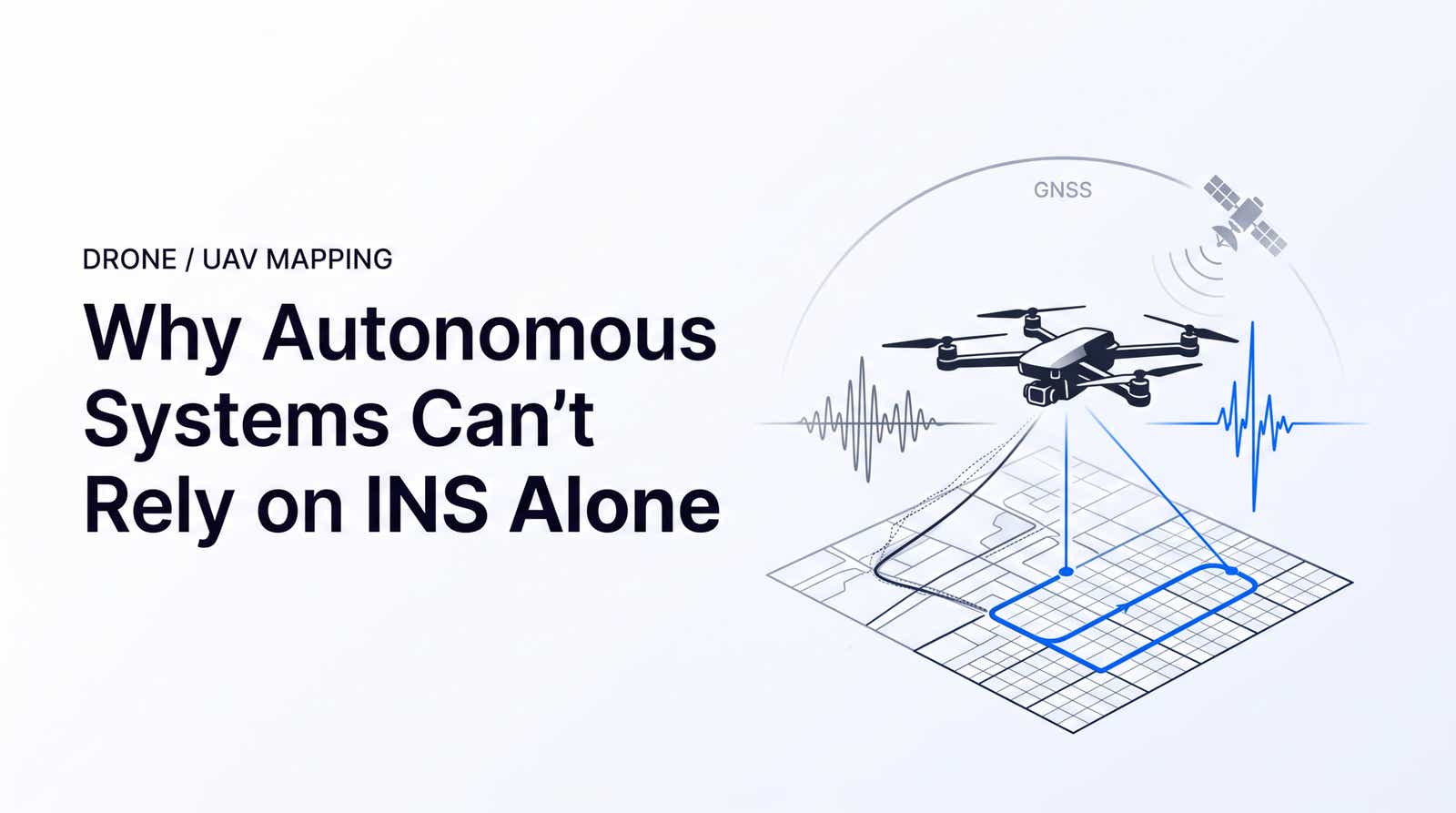
An INS gives an autonomous drone or ground robot a self-contained way to estimate motion when the sky view disappears. It also drifts. Every autonomous platform we see in the field, from mapping UAVs to driverless race cars, hits the same wall: dead reckoning is stable for seconds to minutes, GNSS is stable for hours but loses lock in tunnels and urban canyons, and neither layer on its own reaches centimeter-level positioning. This article walks through why GNSS-inertial fusion plus RTK corrections is the layered stack that actually works.
Estimated reading time: 7 minutes
What is inertial navigation? An INS is a self-contained positioning device that uses an IMU (accelerometers plus gyroscopes) to track motion by dead reckoning. It integrates acceleration and rotation over time to estimate position, velocity, and heading without any external signal, which makes it valuable when GNSS is degraded or denied.
- IMU-only positioning drifts within seconds (consumer grade) to minutes (tactical grade) once external aiding disappears.
- Raw GNSS delivers 2 to 5 m accuracy and fails under multipath, spoofing, or tunnel conditions.
- Fusing satellite fixes with inertial dead reckoning through a Kalman filter, loosely or tightly coupled, covers both weaknesses.
- RTK corrections collapse GNSS error from meters to 1 to 2 cm, tightening the filter's confidence.
- Timing sync and IMU bias stability decide how gracefully the stack degrades during GNSS-denied moments.
Why GNSS Alone Fails: Multipath, Urban Canyons, and Spoofing
Standalone GNSS positioning is nominally 2 to 5 m under open sky and degrades rapidly in real environments (GPS.gov accuracy overview, 2026). Multipath reflections in a downtown corridor add meters of error. A tunnel or dense canopy blocks the signal entirely. Deliberate jamming or spoofing, now documented across commercial drone incidents, can inject false positions before the receiver flags a problem.
For a mapping UAV or a delivery robot, raw GNSS cannot be the single source of truth. The signal disappears exactly where autonomy is hardest: near buildings, under bridges, inside warehouses.
How GNSS + INS Fusion Works: Loosely vs. Tightly Coupled Kalman Filters
Sensor fusion resolves this by treating satellite positioning and inertial sensing as complementary streams. A Kalman filter runs a continuous predict-update cycle: the filter predicts the next state from IMU samples, then GNSS updates that prediction whenever a fix is available. When GNSS drops out, the filter falls back on inertial prediction until a fix returns.
Two architectures dominate:
| Architecture | Input to Filter | Behavior During GNSS Outage | Typical Use |
|---|---|---|---|
| Loosely coupled | GNSS position and velocity solution | Standard, needs 4+ satellites for updates | Most commercial UAVs |
| Tightly coupled | Raw pseudoranges and carrier phase | Can update with 1 to 3 satellites | UGVs, autonomous vehicles |
A tightly coupled architecture keeps updating the filter even when the receiver cannot compute a standalone fix, which matters when a robot cuts between two buildings and sees only two satellites for several seconds.
Where RTK Corrections Fit In: From Meter-Level GNSS to Centimeter Accuracy
Fusion fixes availability. It does not fix accuracy. A Kalman filter can only be as good as the GNSS measurements it consumes. If the raw fix carries 2 to 5 m of error, the fused output stays in that band regardless of IMU quality.
RTK (Real-Time Kinematic) closes the gap by streaming RTCM 3.2 correction data from a reference network to the rover. Fixed ambiguity solutions deliver 1 to 2 cm horizontal accuracy. Inside the Kalman filter, that lower measurement covariance tightens the entire state estimate, including velocity and heading.
For an inertial navigation system with gps at its core, RTK is the layer that turns a lane-level fix into a lane-position fix. Cloud NTRIP services deliver these streams globally without a base station per site.
The Four Phases of GNSS Degradation
Real deployments cycle through four states, and system design lives or dies on how each is handled.
- Available: full-sky fix, RTK fixed, sub-decimeter positioning.
- Degraded: partial obstruction, multipath, dropped constellations; standalone accuracy expands to 2 to 10 m.
- Denied: tunnel, indoor, or jammed; dead reckoning takes over and the inertial drift budget starts burning.
- Reacquisition: the receiver returns to open sky; RTK re-fix latency (typically 5 to 30 seconds on a warm receiver) determines how quickly centimeter accuracy is restored.
In our own work with driverless Formula Student teams, the cleanest handovers happen when the fusion stack accepts RTK corrections as an always-on input rather than switching them in reactively. That design keeps the reacquisition phase short and predictable.
PWR Racing's RT16e driverless car passes through covered pit lanes at speed, forcing the fusion stack to hand over cleanly between GNSS-fixed and inertial prediction every lap. Read the PWR Racing case study.
Additional Aiding Sources: LiDAR, Visual Odometry, and Wheel Encoders
When GNSS is denied for longer than the IMU can bridge, additional aiding inputs keep localization bounded.
- LiDAR with SLAM: point cloud registration against a prior map anchors position in tunnels and warehouses.
- Visual odometry: monocular or stereo cameras track feature displacement; low weight, well suited to drones.
- Wheel encoders: reliable on ground vehicles, contribute forward velocity even in total signal blackout.
- Barometer: constrains vertical drift on drones during hover.
Each aiding source carries its own error model, and the Kalman filter weights them dynamically. For precision positioning for UGVs that move between indoor and outdoor zones, this multi-sensor stack is standard. Teams building RTK-enabled drone navigation lean more heavily on visual and barometric aiding, since wheel encoders do not apply airborne.
IMU Quality and Timing Sync: The Two Factors That Define Resilience
Two engineering variables set how long an autonomous stack survives a GNSS gap.
IMU grade. Bias stability, angle random walk (ARW), and thermal compensation determine the drift slope. A tactical-grade MEMS unit holds in-run gyro bias stability near 1 deg/hr, while an industrial-grade unit sits around 10 deg/hr, a tenfold difference in how fast heading error accumulates during an outage (VectorNav IMU Specifications Explained, 2026).
Timing synchronization. GNSS timestamps arrive with nanosecond precision. IMU samples typically run on a separate clock. If the two streams are not aligned to a shared PPS reference, the Kalman filter fuses stale IMU data against fresh GNSS updates, and the state estimate rotates around a phantom offset. Teams building GNSS for autonomous transport invariably invest in hardware time sync before optimizing anything else in the fusion stack.
FAQ
What is a GNSS aided inertial navigation system?
It is a fusion architecture that uses satellite positioning to bound the drift of an inertial sensor stack. The GNSS receiver provides periodic position and velocity fixes; a Kalman filter uses them to correct the IMU-based estimate, keeping error bounded over long missions.
How long can an INS stay accurate without a GNSS signal?
It depends on sensor grade. Tactical-grade units maintain sub-meter accuracy for several minutes; consumer-grade MEMS units drift into meters within seconds. Adding aiding sensors such as LiDAR or wheel encoders extends usable time significantly.
What is the difference between loosely coupled and tightly coupled GNSS/INS integration?
Loosely coupled fusion feeds the filter with the GNSS receiver's finished position and velocity solution. Tightly coupled fusion feeds raw pseudoranges and carrier phase, allowing updates with fewer than four satellites, which improves resilience in urban canyons.
How accurate is RTK compared to standard GNSS positioning?
Standard GNSS delivers 2 to 5 m horizontal accuracy in open sky. RTK with a fixed ambiguity solution delivers 1 to 2 cm horizontal accuracy, a roughly hundredfold improvement, and reduces vertical error to 2 to 3 cm.
Does RTK work in urban canyons or under tree canopy?
Partially. RTK requires stable carrier phase tracking, which multipath and blockage disrupt. In degraded environments the solution drops from fixed to float (10 to 50 cm) or loses lock entirely. A tightly coupled fusion architecture with a quality IMU bridges these gaps.
What sensors do autonomous robots use to navigate when GNSS is unavailable?
Typical choices are IMUs, LiDAR with SLAM, visual odometry cameras, wheel encoders, and barometers. Each has different error characteristics; a Kalman or factor graph filter combines them dynamically to maintain localization until GNSS returns.
Ready to Add RTK to Your Fusion Stack?
Architecture matters, but the corrections layer determines whether your accuracy budget is measured in meters or centimeters. Stream RTCM 3.2 corrections into your platform for 30 days without a base station.

Owns infrastructure, security, and integrations at RTKdata.