

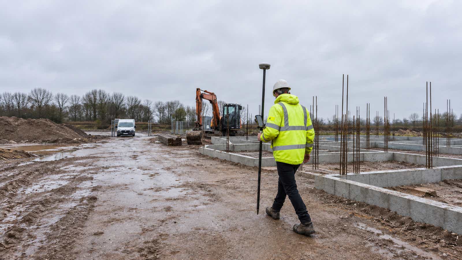
Open sky and spread-out points: use GNSS RTK. Tight tolerances with a clear line of sight, or an obstructed or urban site: use a total station, and under cranes, steel or a partial roof, a robotic total station. The usual answer is both: GNSS establishes site control and the total station handles layout near structures.
The robotic total station vs GNSS RTK decision changes with the job, sometimes within the same shift. A drone team setting ground control on an open field faces different constraints from a crew setting building gridlines beside a steel frame. Start with the required tolerance, coordinate reference and conditions at each point. Then choose the instrument and checks that can deliver an acceptable result.
Quick Answer: Which Tool for Which Job
Use this sequence before committing the crew:
- Open sky, scattered points: start with GNSS, then confirm FIX and check against suitable control.
- Tight tolerances, obstructed or urban sites: start with optical measurement from verified control, with a clear view to the target.
- Cranes, steel or a partial roof: the robotic instrument, set up so columns and moving cranes do not block the prism.
- Mixed conditions: establish suitable control in the open, then transfer it into obstructed areas with the total station.
Robotic Total Station vs GNSS RTK at a Glance
| Capability | Robotic optical instrument | GNSS RTK rover |
|---|---|---|
| Measurement method | Horizontal and vertical angles plus electronic distance measurement | Satellite carrier-phase observations with corrections |
| Line of sight | Required between instrument and prism or measured surface | No optical sight line to the reference station; satellite visibility matters |
| Satellite requirement | Not required for optical observations | Sufficient usable satellite signals and suitable geometry |
| Typical crew | One-person crew at the pole, where site rules permit | One rover operator, where site rules permit |
| Control requirement | Known station and orientation, or a checked resection | Correct reference frame, corrections and checked project transformation |
| Main limitation | Obstructed target view or unsuitable setup geometry | Masking, reflections, correction interruptions and baseline effects |
How a Robotic Total Station Works
The instrument combines angular observations with an electronic distance to calculate a target position relative to its setup. Motorised tracking follows a compatible prism, while a field controller lets the operator measure or stake out from the pole. Prism lock keeps the instrument aimed as the operator moves within its tracking capabilities.
Manual vs Robotic Total Stations
With a manual instrument, an operator usually aims from the tripod while another person positions the pole. Automation can remove that repeated aiming task, but it does not remove the need to identify the correct point, keep the pole stable or check the survey.
What Automation Does Not Change
The instrument still needs a valid position and orientation. A backsight establishes direction from the setup, whereas resection calculates a setup using observations to known control. Reflectorless measurement can reach visible surfaces without a prism, but surface properties and incidence angle affect the measurement.
How GNSS RTK Works in the Field
RTK uses carrier-phase measurements with reference observations to estimate the rover's position. The receiver resolves carrier-phase ambiguity to obtain a fixed solution. Our guide explains how RTK achieves centimeter accuracy and the conditions behind that result.
Where Corrections Come From: Base, CORS and Network RTK
Corrections can come from an on-site base, a CORS network or a commercial service. NTRIP carries data over an internet connection, whereas other setups use radio. Some networks offer VRS, a virtual reference station generated for the rover's vicinity, while others select a nearby physical reference station.
RTKdata's documented AUTO service selects the nearest reference using the rover's GGA position. Its network settings also describe regional and global reference-frame options. For GIS managers, that choice decides whether every team's data lands in one datum; a correction subscription does not correct a mismatched project coordinate system. Network corrections also mean no base station to buy, set up and guard on each site.
What the Rover Needs to Hold a Fix
The receiver needs usable satellite observations, compatible corrections and a functioning data connection. Antenna placement, obstruction, baseline distance and changing atmospheric conditions affect performance. RTKdata's accuracy FAQ states approximately 1–2 cm horizontal and 2–4 cm vertical under open sky with RTK FIX. Those are conditional receiver-position figures, not guaranteed drone-map accuracy.
Accuracy: Relative vs Absolute
Total station accuracy is especially valuable when nearby features must have precise geometry relative to one another. GNSS can efficiently connect measurements across an open site to a defined reference frame. Both can produce project coordinates, but neither escapes errors in the control used to establish them.
For example, the Leica TS16 data sheet specifies 1 mm + 1.5 ppm for single prism distance measurement and 2 mm + 2 ppm for single measurements to a surface, under its stated conditions. These are distance specifications, not complete point-coordinate tolerances. Angular uncertainty, centering, target height and control quality also contribute.
Incorrect control can displace a precise building grid. Conversely, a correctly referenced rover may miss tight layout tolerances.
Fix vs Float and Why It Matters
FIX indicates resolved integer ambiguities, whereas FLOAT indicates that they remain estimated as non-integer values. Do not accept FLOAT as a substitute when the job requires fixed centimeter-level observations. A position shown on screen is not evidence that its uncertainty meets the specification.
FIX alone is also insufficient. Trimble's initialization guidance recommends periodically re-measuring previously measured points with a new initialization, as a check against multipath.
Setup Discipline: What Each Instrument Demands
Before accepting measurements, check:
- Optical setup: stable tripod, centering and level, verified orientation, correct prism constant and target height, plus an independent check point.
- Satellite setup: antenna height and measurement convention, correction source, datum and height system, solution quality, plus observations on known control.
- Shared project settings: units, grid versus ground distances, transformation parameters and consistent point naming across both controllers.
Total station accuracy cannot compensate for an incorrect target height, just as a stable FIX cannot compensate for the wrong datum.
Where GNSS RTK Struggles
Buildings, roofs and trees create satellite masking, so the receiver loses direct views of parts of the sky. Reflective steel, glazing and nearby structures can create multipath, where signals arrive along additional reflected paths.
Trimble's RTK guidance identifies multipath, satellite geometry and distance from the base as accuracy factors. A rover may continue reporting coordinates while the solution changes or quality deteriorates.
Our explanation of why RTK fix drops out covers these mechanisms. For larger sites, review RTK accuracy over baseline distance. Moving farther from a physical reference can reduce the similarity of atmospheric errors; internet delivery does not remove that effect.
Where a Robotic Total Station Struggles
A worker, excavator or column can obscure the prism. With several prisms or reflective objects in view, wrong-target acquisition is another risk.
Trimble's Autolock documentation explains how target ID can distinguish a target and how search-only identification differs from checking during measurement. Match the controller settings to the actual target and instrument rather than assuming identification stays active in every mode.
A partial roof may favor optical work because it blocks satellites, but columns and moving cranes can still interrupt observations. Position the instrument to protect sight lines and verify orientation after a disturbance. Side by side:
| Failure point | GNSS RTK rover | Robotic instrument |
|---|---|---|
| What blocks it | Buildings, roofs and trees masking the sky | Workers, plant or columns between instrument and prism |
| Risk of a wrong answer | Multipath from steel and glazing while coordinates keep displaying | Lock on the wrong prism or a reflective object |
| How you catch it | Solution state, FLOAT flags and a check shot on a known control point | Target ID checked during measurement, plus a check point |
| Recovery | Reinitialize under open sky, then re-measure a known point | Reacquire the prism or add a controlled setup |
Workflow by Workflow: Which Tool to Reach For
| Workflow | Starting choice | What could change it? |
|---|---|---|
| Open-field topo | GNSS RTK | Trees, weak correction coverage or tighter height tolerances |
| Building gridline layout | Total station | Control quality, intervisibility and the specified layout tolerance |
| One-person stakeout | Either | Open sky favors a rover; visible targets and tight local geometry favor optical work |
| Urban survey | Combined approach | Use suitable open control locations and carry measurements into obstructed areas |
| Machine control | System-dependent | GNSS suits open earthworks; compatible optical tracking can serve demanding local work |
| Deformation monitoring | Engineered monitoring design | Total stations suit relative target movement; GNSS may support open-sky continuous monitoring |
| Drone ground control | GNSS in open areas; optical transfer where needed | Control distribution, height requirements and independent checkpoints |
The table is a starting rule rather than a substitute for a project specification. For drone work, measure checkpoints independently of the points used to constrain the model; our comparison of drone mapping vs traditional survey covers where each fits.
On cost, the two are different structures.
| Cost item | Robotic instrument | GNSS RTK with network corrections |
|---|---|---|
| Instrument | Capital purchase: Sokkia iX-605 US$19,500; Topcon GT-1202 US$26,900 (Topcon Solutions, September 2026) | Rover receiver and field software |
| Not in the box | Controller, prism and field software (absent from both box lists) | No base station needed on site |
| Recurring | Servicing and calibration | RTKdata subscription: $40 per month or $400 per year for one concurrent device (pricing) |
Using Both: Control with GNSS, Layout with the Total Station
In practice the answer is usually both. The combined workflow starts with suitable site control in open locations. Verify the coordinate reference and observe enough redundant measurements to support the required tolerance. Then use the optical instrument to transfer and densify control around the structure.
GNSS-derived control does not automatically meet every construction tolerance. Where requirements are tighter, strengthen the control network and use appropriate independent checks or leveling. Accurate optical observations preserve local geometry, but they do not erase uncertainty inherited from the starting coordinates.
Record heights, transformations and observation methods so the next crew can reproduce the reference. Explore RTK for surveying and RTK for construction to assess the correction-service part of that workflow.
FAQ
Which is more accurate, RTK or total station?
A total station generally suits tighter relative tolerances over short to medium distances from verified control. GNSS RTK can provide centimeter-level positioning under suitable open-sky conditions with compatible corrections and a checked fixed solution. Neither is universally more accurate: compare the required horizontal and vertical tolerances, measurement distance, setup and control quality. Check either method against independent control before accepting the work.
What are the key differences between total station surveying and GNSS surveying?
A total station reads angles and distance to a visible prism or surface. GNSS surveying uses satellite signals; RTK adds reference data for precise real-time positioning. Optical work needs clear target sight lines, while GNSS needs usable satellite visibility. This makes GNSS practical for scattered open-sky points and optical measurement useful for detailed layout near structures. Both methods can share a verified project coordinate system.
What is a robotic total station?
It is a servo-driven optical instrument that measures angles and distances and automatically tracks a compatible prism. A field controller lets one operator measure or stake out from the pole, provided sight lines and site rules allow it.
How much does a robotic total station cost?
The purchase cost depends on the model, configuration and included equipment. Request an itemized quote covering the instrument, controller, targets, software and support. Compare servicing and training costs too; an instrument-only price is not the cost of a complete working system.
What are the disadvantages of a total station?
It needs a clear view to the target and a verified setup. Obstructions can interrupt measurements and require additional setups. Robotic instruments can lose prism lock or acquire the wrong target, so target identification and independent checks remain important.

Leads marketing, growth, and customer-facing communication at RTKdata and builds the demand engine across paid, content, and outreach.